
We are Manufacturer, Supplier, Exporter of Harmonic Filter Capacitors, Low Voltage Capacitors, LV MV HV Capacitors from Sangli, Maharashtra, India
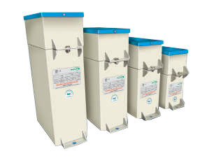
Magnewin Energy Pvt. Ltd. offers Harmonic Filter Capacitors designed for low voltage reactive power management, helping industries improve power quality and efficiency. Our capacitors are manufactured in a top-tier facility in Sangli, Maharashtra, using advanced technology and adhering to IS standards. These capacitors are essential for managing reactive power, especially in environments where inductive loads like motors and transformers dominate, leading to energy inefficiencies.
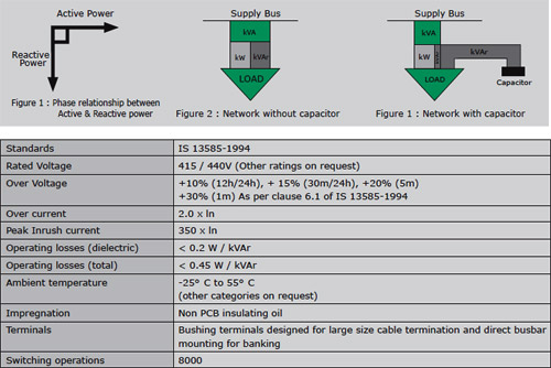
Reactive Power Management in Harmonic Filters
In industrial setups, reactive power often leads to increased current flow, voltage drops, and system losses, impacting efficiency and increasing costs. Magnewin’s Harmonic Filter Capacitors counter these effects by reducing reactive power demand, minimizing kVA, and improving power factor, ultimately lowering electricity costs. Applications
- Power factor correction in low voltage (LV) networks
- Automatic power factor correction panels (APFC) with contactor or thyristor switching
- Fixed power factor correction systems
- Harmonic filtering
Key Features
- High-Quality Dielectric: Bi-axially oriented double hazy film ensures excellent oil impregnation.
- High Inrush Current Capacity: Withstands high peak inrush currents, essential for robust performance.
- Compact Design: Compact, easy to mount, and suitable for flexi-banking.
- Low Losses and Noise: Efficient design with minimal operating losses.
- Long Life: Expected life of at least 20 years, ensuring durability and reliability.

Safety and Protection
Our capacitors are designed with multiple safety features:
Our capacitors are designed with multiple safety features:
- Internal Fusing: Provides protection against short-circuit conditions.
- Non-Hazardous Oil: Uses non-PCB, environmentally friendly oil.
- Discharge Resistors: Externally fitted discharge resistors ensure safe handling.
- Thermal Switch: Includes temperature protection to prevent overheating.
Installation and Operational Guidelines
To optimize capacitor performance, consider these factors:
To optimize capacitor performance, consider these factors:
- Internal Fusing: Provides protection against short-circuit conditions.
- Temperature Management: Keep capacitors in well-ventilated areas; implement forced cooling if necessary in detuned reactor setups.
- Over Voltage & Current Limits: Operating above recommended levels will reduce capacitor life. Ensure current and voltage stay within specified limits.
- Switching and Discharge: Use fast-acting capacitor contactors to handle inrush currents. Capacitors must discharge to 75V within 3 minutes before switching back on.
Additional Information
- Earthing: Proper earthing is essential to ensure safety and prevent operational issues.
- Mechanical Protection: Avoid using capacitors with any visible damage. Report leaks or deformities to the manufacturer.
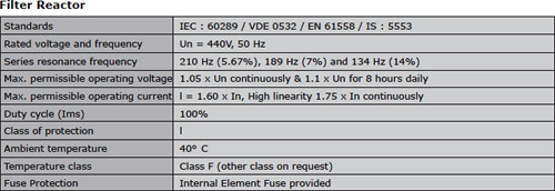
- Resonance Avoidance: In harmonic-rich environments, use detuned reactors with capacitors to prevent resonance and current amplification.
Our Harmonic Filter Capacitors are tested in-house according to the latest IS 13585 standards, ensuring reliability and performance in challenging industrial environments. For more details or specialized applications, contact Magnewin Energy Pvt. Ltd.
Note: Product improvement is a continuous process. For the latest information and special applications, please contact us